We all love our vids and pins. And for those of us that repair and/or restore older games, most of us are proud in what we have done to return them working again and bring them back to their former glory. And we might like the idea of sharing them with others at an event like Free Play Florida (FPF) where we can proudly display our games to others and let them enjoy them as much we we do. But if you are gonna contribute games to a Free Play event, there are some things to keep in mind.
(Note: I am strictly speaking for myself here, and not as anyone that is affiliated with FPF. These are my own opinions and experiences.)
Information is this document is from personal experience with these beasts and some was stole^H^H^H^H^H… um, I mean… inspired… from many sources including official Atari docs (wiring diagrams, schematics) and Internet-based sources from authors that are far smarter than I, including:
Some of the information in this document may be incorrect!!!
The reader (um, that means YOU) assumes all risk of using or misusing this information. I am not responsible if the information in this document results in damage to your AR-II, damages your game, burns your house down, gets your sister pregnant, kills your dog, causes you to get divorced, etc. By continuing to read this document and/or apply the information contained within, you acknowledge the above and assume all risks of using the information provided.
We Will Start by Just Getting This Out of the Way…
The notorious SENSE mod. The arcade community seems split on this one. Not exactly a 50/50 split, but more people seem to recommend performing the mod. The rest vote for keeping the SENSE circuit intact, and “simply” performing proper maintenance and/or other mods on the game to alleviate the connectors heating up and burning, which is the primary reason for suggesting that one should disable the SENSE circuit.
Personally, I prefer to learn from history – suggesting that one correctly maintain their game and keep their edge connectors clean is great. But we all know that people just do not do it. So personally, I suggest performing the mod, and directions for doing so are included in this document. Besides, I think it is better to find out that your connectors are going bad by a voltage drop causing the game to stop working, not by your connectors getting too hot and deteriorating further.
That said, you will see people talk about “bulletproofing” an AR-II, and then they simply go about describing the SENSE mod.
THIS IS NOT BULLETPROOFING!
Anyone that says that simply performing the SENSE mod is bulletproofing1 an A/R-II is lying to you or just does not know any better. Why? Because if the +5V regulation fails it is still possible to end up with more than +5V over the +5V line, which could damage any board connected to it. What kind of “bulletproofing” is that? (Shameless plug: that is why I designed a PCB with an adjustable crowbar circuit – THAT is how you bulletproof an A/R-II!) Anyway – rant over… information on an easy way to perform the SENSE mod is shown below where I document connector J7.
Meet the Atari Regulator/Audio II (mod -02)
This component, affectionally referred to as the A/R-II (“A Are Two” even though calling it the R/A-II would be more correct) was used in many of Atari’s games from the ‘70s and ‘80s. It exists in various forms, from the original Regulator/Audio board used in early B/W games like Asteroids and Atari Football, to the Regulator/Audio II used in many different color games to about the mid ‘80s (e.g. Centipede, Dig Dug, Kangaroo, Missile Command, Pole Position, Tempest, etc.), to the Regulator/Audio III.
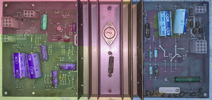
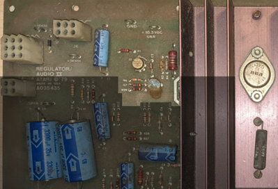
Its primary purpose was to supply necessary voltages for the game (logic, audio, and sometimes things like the odd voltages required to erase an EAROM), as well as provide audio amplification. Different versions of the board provided different features like different voltages, more amperage, etc. The image below shows a -02 version.
Figure 1 – AR-II Sections
The board can be roughly divided into 3 areas that are shaded purple, green, and bluein the above image. The middle and upper-left areas are +5V regulation, the lower-left is audio amplification, and the right side is secondary voltages (-5V, +12V, and +/-22V). It is worth mentioning that both “halves” of the board are logically separate. You can apply power to only the left side and get your +5V and audio amps. And you can apply power to only the right side and get your secondary voltages. Both sides do not have to be powered up at the same time.
The connectors are consistent between other versions and revisions of the board, so it may be possible to substitute one for the other depending on the voltages and/or features required. For example, a -03 can usually be used to replace a -02.
Connectors
We will go through the connectors in order of their designations.
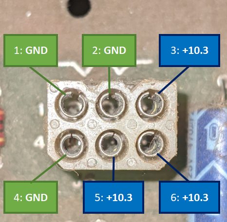
J6 – Main Power Input
Figure 2 – AR-II Connector J6
This connector supplies the power required to produce the regulated +5V and audio amps. Note that the +10.3VDC input is unregulated and may normally measure a couple of volts higher when not loaded, such as if you meter it directly on the power brick.
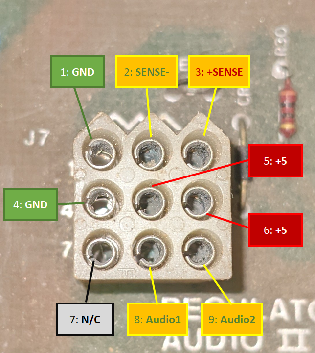
J7 – Main Power Output and Audio Input
Figure 3 – AR-II Connector J7
This connector supplies the regulated +5V as well as the SENSE lines. It also is where unamplified audio comes into the board.
SENSE Circuit Description and the SENSE Mod
So, how about we stop here for a second to talk about SENSE. You may have heard of the infamous SENSE circuit on these boards, but what does it really do? Well, it is supposed to detect a voltage drop between the power supply and the game’s board. On the game’s PCB the +5V is routed to +SENSE, and GND (the +5Vreturn) is connected to -SENSE. The A/R board uses the voltage coming back on the SENSE lines to determine if it needs to bump up the voltage to compensate for any voltage drop that occurred on the way to the game’s PCB. Sounds like a good idea at first, right?
Well, now throw in a failing +5V connection to the board – like a dirty connection or a physically failing one. As more and more voltage is lost, the SENSE circuit will keep boosting the voltage, which can lead to overheating and exacerbate the failing connection. Remember that the +5V and +SENSEare connected on the game board? Well, if the +5V connection fails badly enough, the game might try to draw current over the +SENSEline. This is the cause of the infamous smoking of R30 (and sometimes R29) – the game is trying to draw multiple amps across that poor little ¼ or ½ watt resistor.
So, the SENSE mod tricks the SENSE circuit into always seeing exactly what the A/R board is putting out. This is done by connecting +5V and +SENSEtogether, and GND and -SENSEtogether, on the A/R board itself. The easiest(?) way to do this is to turn the A/R board over and solder a jumper between pins 1 and 2, and another one between 3 and 6 on connector J7. Note that after doing this, you may have to manually adjust the +5V pot to get a solid +5V at the game board.
It is also worth noting that if you ever need to bench test the board or adjust the voltage using the pot at R8, make sure that the +SENSEline is connected back to the +5V line either via the mod or by connecting-up a game board. The +SENSEline is what is connected to the feedback input on the +5V regulator and and this feedback circuit is necessary for the board to work correctly.
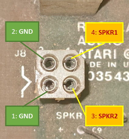
J8 – Speaker (Amplified Audio) Output
Figure 4 – AR-II Connector J8
This is the amplified audio (Speaker) connection. If you are used to seeing positive and negative speaker signals, consider the SPKR1 and SPKR2 signals to be the positive ones, and the GND to be the negative ones.
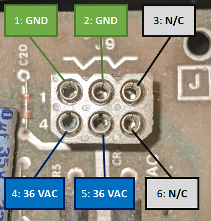
J9 – Secondary Power Input
Figure 5 – AR-II Connector J9
This connector provides the 36VAC (note – AC,not DC like on J6) input voltage to the board which is necessary to generate the additional +12, +/-22, +/-15, and -5 voltages. Not all A/R boards are stuffed to produce all the secondary voltages. On the board shown in this document, the area that would be used to produce the +/-15V is unpopulated.
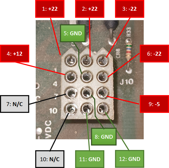
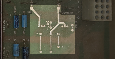
J10 – Secondary Voltage Output
Figure 6 – AR-II Connector J10
This connector provides the additional voltages produced from the 36VAC provided on connector J9. (Pins 7 and 10 would be the +/-15V if it was present on this board.) Also note that the +/-22Vis unregulated and directly connected to the bridge’s filtered output, so do not be surprised if you see a higher voltage when unloaded.
Operation
Here I will try to describe how this A/R board works.
Primary +5V Supply
The primary +5V supply derives from the +10.3VDC input to the left side of the board. This uses a LM305 regulator marked Q1 and transistors Q2 and Q3 to boost the output current. Q2 (a TIP32) acts as a driver for the larger Q3 (a 2N3055).
Excessive voltage or no voltage on the +5V line may be caused by a failed 2N3055 or a failed LM305. Suspect the 2N3055 if you have +5V present, but it drops when you load the +5V line. If you have no +5V output and the audio amps also appear to not be working, verify the +10.3VDC input voltage from the powerbrick.
Figure 7 – AR-II Primary Voltage Area
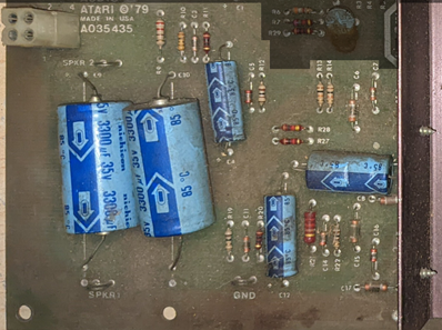
Audio Amplifiers
Audio amplification is provided by the two TDA2002(AV) amplifiers.
If you are having problems with distorted sound, I would start with the two larger output coupling caps, C9 (SPKR1) and C10 (SPKR2) before looking at the amplifiers themselves.
Figure 8 – AR-II Amplifier Area
Secondary Voltages
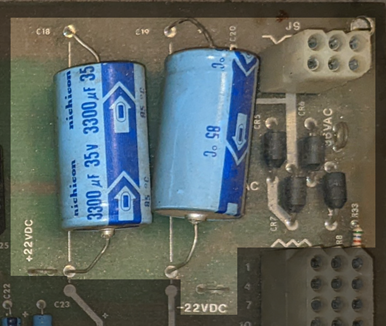
The secondary voltages derive from the 36VAC input to the right side of the board. This AC goes through a traditional full-wave bridge rectifier constructed using four discrete diodes (CR5, CR6, CR7 and CR8) with the two large smoothing caps C18 and C19. Its output is used to produce all the secondary voltages. If you notice excessive ripple on any of the secondary voltages, especially the +/-22Vones, check C18 and C19.
If you notice a sudden voltage drop on the secondary voltages, or a complete loss of one of the polarities, check for failed diodes in the rectifier (i.e. the full-wave rectifier may have become a half-wave rectifier).
+/-22V Unregulated Supply
This is directly connected to the post-smoothed rectifier output. If the incoming 36VAC is good and all the rectification and filtering is working correctly, you should see these voltages. These outputs might be the best ones to look at to help spot rectification and filtering issues. Remember this is an unregulated output so you may see a higher voltage here when unloaded.
Figure 9 – AR-II Secondary Voltage Input
+/-15V Supply (Not present on this board.)
These voltages are produced by two regulators that use the unregulated +/-22V as inputs. The positive regulator is a 7815 and is connected to the positive side of the unregulated +/-22V, and the negative one is a 7915 that is connected to the negative side of the unregulated +/-22V.
Figure 10 – +/-15V Voltage Area
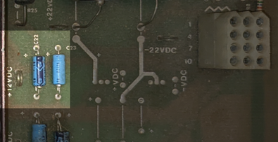
+12V Supply
This voltage is produced by a 7812 regulator connected to the positive side of the unregulated +/-22V.
Figure 11 – +12V Supply
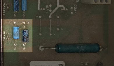
– 5V Supply
This voltage is produced by a 7905 regulator connected to the negative side of the unregulated +/-22V.
Figure 12 – -5V Supply
Troubleshooting
This section covers a few things that might help with troubleshooting and repair of an A/R-II.
First is a good adjustable power supply to produce the +10.3V for the primary side and either a transformer that will output ~36VAC or a variable one for the 36VAC for the secondary side. I recommend working with one side at a time.
Next is to get a good quality 2-ohm, 20 W cermet resistor. When briefly connected between +5V and GND it will pull 2.5 amps and I believe this is a suitable load to test the +5V line with.
If testing on a bench, be sure to either have the sense mod performed or jumper together the +SENSE and +5V pins, and the -SENSE and GND pins.
Problem/Symptom
Possible Cause(s)
+5V is present and seems stable when measured while unloaded but drops to a much lower voltage when loaded.
1. The 5V regulator may have failed.
2. The 5V regulator is working, but the board cannot provide the additional current that would normally be provided via Q2 and/or Q3, so one or both may have failed (likely just Q3).
No +5V present, audio amplification seems to be working.
1. This could mean that the 5V regulator has failed.
2. This could mean that the 5V regulator is working, but the board cannot provide the additional current that would normally be provided via Q2 and/or Q3, so one or both may have failed (likely just Q3).
No +5V and no audio amplification.
Check 10.3VDC input and fuses on power brick.
One or more audio channels is not working.
The amplifier for that audio channel may have failed – the TDA2002 at Q5 for SPKR1 and/or the one at Q7 for SPKR2.
One or more audio channels are distorted.
The output coupling cap for that audio channel may be leaky and need to be replaced – C9 for SPKR1 and/or C10 for SPKR2.
+5V has excessive ripple present or the game is experiencing excessive crashes, resets, visual artifacts, odd behaviors, etc. Sometimes an audio hum can also be heard.
Check the large filtering capacitor (the “Big Blue”) on the power brick.
Secondary voltages have excessive ripple present (especially noticeable on the +/-22V).
Check the two large filtering capacitors on the right side of the board – C18 and C19.
Secondary voltages are missing a polarity or a reduction in output is voltage is present
One or more of the diodes that comprise the full-wave bridge rectifier on the right side of the board may have failed – CR5, CR6, CR7 or CR8.
Missing one or more of the regulated secondary voltages.
The regulator for the associated voltage may have failed – the 7905 for the-5, or the 7812 for the +12.
Pulling too much current on the 36VAC (blown fuses).
One or more diodes in the bridge may have shorted – CR5, CR6, CR7 or CR8.
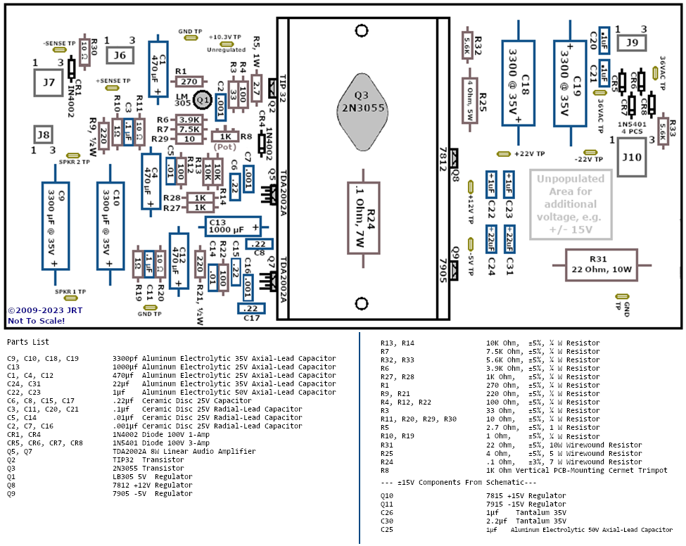
Component Layout and Parts List
The following is a redrawn parts layout for this A/R-II board. Location may not be precise or exact down to a millimeter but should allow you to locate and identify components of interest. A parts list is also included.
Figure 13 – AR-II Layout and Parts List (Click for full size image)
Modifications
Converting a -02 to -03
The version -03 of the AR-II is almost identical to the -02 but with a few changes for the increased current demands of Missile Command (and Monte Carlo?). The differences are:
R25 – a 4 ohm 5W resistor, is replaced with a jumper (or you might see a black zero-ohm resistor)
R31 – a 22 ohm 10W resistor is replaced with a 15 ohm resistor
This also means that you should be able to safely substitute a -03 for an -02 if necessary.
[1] You do not wear a bulletproof vest to prevent things from going wrong, you wear one for when things do go wrong. If you are not able to completely prevent or robustly handle a catastrophic failure, I would suggest that you are notbulletproofing.
I have learned through many years of posts, sales, people, auctions, and similar experiences that there are certain words and phrases that you need to watch out for when buying games, boards, etc.
Untested
The first one, and it is a biggie – UNTESTED. Here is the truth: if dealing with a whole game, and it has an intact power cord, it is never “untested” – somebody tried to plug it in and power it on, guaranteed. When dealing with intact games, presume “untested” means “I plugged it in, it did not work” – in other words, “broken.”
Now, sometimes “untested” really does mean untested. For example, if someone just got a great bulk deal on a bunch of boards, and want to move them quickly, they may not want to go through the time and effort of testing each one. For example, it is not worth building an adapter for a board that sells for $50 working when I can sell it for $30 untested – I would spend more than $20 of my time and materials building that adapter.
Things like power supplies may legitimately be untested because they might not want to risk damaging a board because of a bad power supply (not everyone has a rig to properly test supplies under load). Same goes for controls, coin mechs, etc. Might not be worth the time to connect and try out each one.
In general, just presume that Untested means the same as Broken. That way, you are never disappointed.
Worked [time] ago when I put it into storage, on the shelf, etc.
This is another one. “It worked 6 months ago when I put it into storage,” or “it last worked two years ago before I put it on the shelf.” Same as above – play it safe and consider that to mean untested or just broken.
Correctly Manage Your Expectations Before You Try to Sell Your Arcade Game
Something I see far too often are outlandish prices when uninformed people try to sell a game. I usually see this with someone that originally overpaid (badly) and is trying to make their money back or thinks all games appreciate in value. For example, “I bought this Street Fighter II 10 years ago for $1500(!) and I am sure it is worth $2500 now!”
First: It Is Not Worth What Google Tells You
Occasionally I see someone that has a busted-ass Pac-Man, in a generic converted cabinet with water damage, and a dim monitor, and they Google “Pac-Man Sale Prices” and then think that they can sell it for $1200. And have the audacity to believe they are getting low-balled when someone offers $250.
No, you are not getting low-balled. You just did your search (“research”) incorrectly. You shoulda Googled something more like “converted damaged Pac-Man prices.” But hey, you did not know any better. Take the advice of people that know more than you about things like this.
Also, just because someone paid $xxx for that game in the past does not mean that anyone will now.
Second: It Is Not Worth What eBay Tells You
Some people search eBay for prices and use the final sale price. But before you do that, make sure your game matches up perfectly with the listing you are looking at for your “research.” Do not try to compare your “home use only” Star Trek pinball with one on eBay that was clean, shopped, with new rubbers and no peeling paint on the backglass or playfield.
And, remember: that price is the price that ONE person was willing to pay. Look at the bidding history, if you can, to see what most people were willing to pay.
On Bob Roberts site, there is (or was, if the link is broken by the time you read this) a scan of a page that details how to add the missing parts to the Sanyo 20-EZ monitor chassis to allow it to perform video inversion. Since the page was scanned and not run through an OCR process, the text is not searchable. As a service to the arcade collecting/repair community, I provide this HTML based, searchable version of the document.