Well, like the title initially asks, can you really “bulletproof” an Atari AR-II board? From what I have found on the Internet, and older material like Star Tech Journals, the answer really is no. Pretty much all sources that mention “bulletproof” and “AR-II” on the same page are only taking about performing the Sense mods, and nothing else.
A small amount of pages mention replacing parts (caps, regulators, etc.) due to their age, but that is not bulletproofing either – that is just a good idea. But I think I can actually bulletproof it, and maybe other power supplies as well.
For me, bulletproofing means to take steps to either prevent things from going wrong, or having something in place to protect things when they do. For example, the LV2000 was something used to bulletproof the low-voltage section on a vector monitor, and once you used one you seldom had any more problems with it. So, using an LV2000 was a way to bulletproof it.
Years ago, when I was reading about things like AR-IIs having their regulators go bad and doing really bad things like putting 7+ volts on the 5v line (killing most of what was connected to it), I wondered if it was possible to have a voltage detector that would do something, like open a relay, if the voltage got too high. Sounded simple enough but wondered why no one ever did it.
Looking further into it, I learned about crowbar circuits which are designed to short out a circuit (generally resulting in a blown fuse, tripped breaker, or power supply shutdown) and discovered that companies made voltage sensing chips that could be used to implement a crowbar circuit. The Motorola (later On Semiconductor) MC3423 was of particular interest to me.
Back in ’09 while between jobs, I decided to try to implement something. It ended up being a small tangle of wires and parts on perf board, but it worked and did what it was supposed to do – I turned up the voltage and it blew the fuse. I started a new job soon thereafter and never thought about it again.
However, I recently came across a post in one of the arcade repair related groups I frequent which was discussing bulletproofing an AR-II. It turned out that not much had changed in the past 10 years or so – people would mention “bulletproofing,” and then only talk about doing the Sense Mod with the occasional parts replacement. I decided to dust off the old idea and take a stab at designing my first PCB. As I was working with the schematic I realized that it could have applications beyond an AR-II, so I generalized it a little more and made it easy to connect to any power supply.
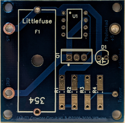
The result is a little PCB that can be used to help prevent damage via over-voltage situations:

Likely not the best-designed PCB out there, for sure, and after using it I definitely see improvements to make for the next spin if there is one. But it is easy to populate and solder, even if the dual-purpose resistor pads (they can support both thru-hole and SMD resistors) seem to want to suck up solder from the other side of the board.
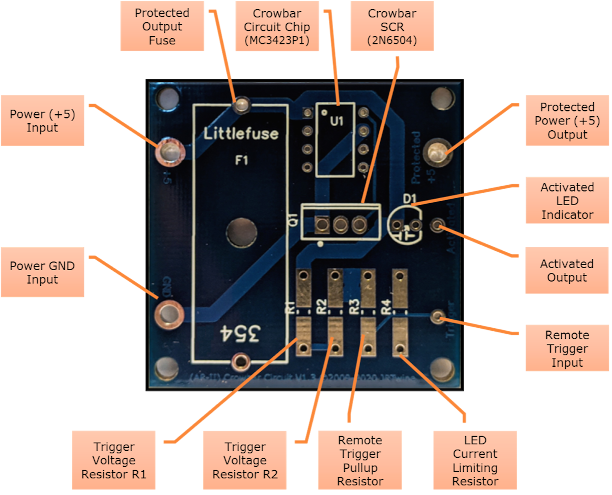
The board is very easy to use. You apply your power (+5/VCC and GND) on the left side, and you have a crowbar protected output on the right. The extra holes in the corners are for mounting, and the two smaller holes, Trigger and Activated, allow for remote activation of the crowbar circuit, and indication that it has been tripped, respectively.

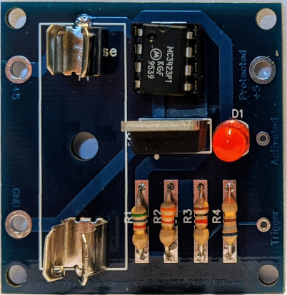
On the above board, the following resistor values are used:
R1: 3.9K
R2: 3.3K
R3: 1K
R4: 410
R1 and R2 can be adjusted to change the voltage trigger point according to the formula in the in the MC3423 datasheet: 2.6v × ( 1 + ( R1/R2 ) ). R3 is the pull-down for the remote activation trigger, and R4 is the current-limiting resistor for the LED.
This particular circuit can operate up to around 11v VCC without a low-value resistor added to the gate of Q1. It is essentially the basic circuit implementation from the datasheet with the addition of the indicator LED and separation of power into the fused and unfused VCC (+5) voltages. This allows the circuit to continue to function after activation and keeps the LED illuminated which lets you know if the fuse was blown due to the crowbar kicking in or because the draw from the connected circuit was excessive and had nothing to do with voltage. It also provides a visual means to test the operation of the circuit.
Populated as shown, the circuit has a calculated trigger of ~5.67v but has an actual trigger of 5.58v and handles an input of at least 15.5v without without letting the smoke out of anything (I discovered this when I accidentally ticked up the wrong digit while testing with my adjustable power supply). With a supply of about 4.5 amps or higher, the fuse blows immediately when triggered. Lower amperage values will cause the fuse to glow and then blow, but it takes longer. A corresponding voltage drop along the output side takes place while this is happening.
I also built a second one with a higher current limiting resistor and different values to try to get a trigger point at 7.01v by changing the resistors as follows:
R1: 5.6K
R2: 3.3K
R4: 680
This yielded an actual trip point of 6.85v, but is close enough to prove the workings of the circuit (and close enough to protect things from an AR-II trying to put out 7v?). Also notice the fuse clips instead of the fuse holder. I just clipped one leg off each fuse holder and soldered the remaining leg. Not the most secure, but good enough for testing. It is also possible to wedge a 10K pot in for R2 and provide a variable trigger point that should go as high as ~10.4v. (Or use a pot for both R1 and R2 and then you have a much wider range to work with.)
The idea of this board was to introduce it between the +5 output of an AR-II and the game board. That is why the PCB specifically mentions “AR-II” and “+5” on it. But it has uses beyond just that. It can be used to implement a crowbar for other voltages (>= 5v) as well, and can work with other power supplies.
I already can see improvements I want to make if I respin the board. These include larger text by the power points, getting the text on the silkscreen and not “buried” under the mask, extra holes to be able to use fuse clips, additional LEDs (for Power, Protected and Activated), maybe a (multi-turn) pot that would allow you to dial in the desired trigger voltage point (a 30K pot would allow you to dial the trigger voltage upwards of 25v) , and finally a resistor for the gate of Q1 that would allow a wider operating voltage.
So! Anyone interested in actually bulletproofing something?!? I have a few other techies playing around with the board to get their feedback on it. LMK if you are interested in trying it out.