Quadrature Encoding
…is the method used by mechanical mice, trackballs, and spinners like those used on Tempest and Arkanoid. It works by attaching a movement axis to a slotted wheel and placing the slots in between two optoisolators or optos. When talking about Quadrature Encoding, the two signals from the optos are sometimes referred to as Clock and Data.
(So I was looking at a device that converted trackball inputs into analog/counter data and I thought it might be a good idea to write a quick refresher on what quadrature encoding is.)
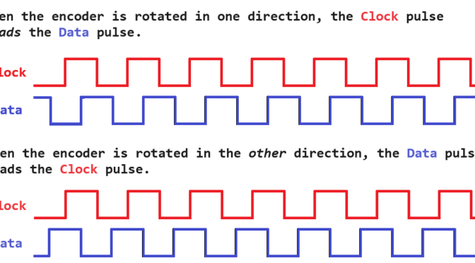
As the slots move through the optos it causes a repeating pattern of pulses. Since two optos are used, one gets broken before the other. This means that one will pulse high before the other (or one will “lead” the other) depending on the direction the wheel is rotating. This results in predictable, deterministic behavior: in one direction, Clock will generate a pulse before Data. In the other, Data will generate a pulse before Clock.
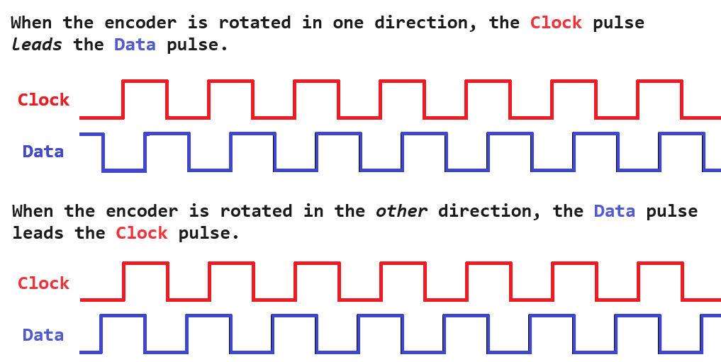
In the above image, the top waveforms show an example where the Clock signal pulses high before the Data signal does, and the pattern repeats in a monotonous fashion. The bottom waveforms show the opposite where the Data signal pulses high before the Clock signal does.
Another way to think about it is to sample the Data signal at the rising edge of the Clock signal. At the time Clock goes high, the Data signal will either be low or high, and that determines the direction of travel. Some simple pseudocode for the geeks:
when Clock
    direction := Data   // 1/High or 0/Low
So when you think about it, is it rather simple and only requires two signal (or GPIO) lines. And there you have it — a simple description on quadrature data and how to use it.