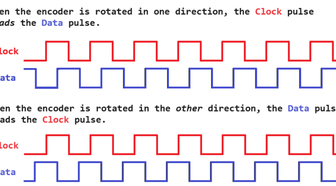
…is the method used by mechanical mice, trackballs, and spinners like those used on Tempest and Arkanoid. It works by attaching a movement axis to a slotted wheel and placing the slots in between two optoisolators or optos. When talking about Quadrature Encoding, the two signals from the optos are sometimes referred to as Clockand Data.
Information is this document is from personal experience with these beasts and some was stole^H^H^H^H^H… um, I mean… inspired… from many sources including official Atari docs (wiring diagrams, schematics) and Internet-based sources from authors that are far smarter than I, including:
Some of the information in this document may be incorrect!!!
The reader (um, that means YOU) assumes all risk of using or misusing this information. I am not responsible if the information in this document results in damage to your AR-II, damages your game, burns your house down, gets your sister pregnant, kills your dog, causes you to get divorced, etc. By continuing to read this document and/or apply the information contained within, you acknowledge the above and assume all risks of using the information provided.
We Will Start by Just Getting This Out of the Way…
The notorious SENSE mod. The arcade community seems split on this one. Not exactly a 50/50 split, but more people seem to recommend performing the mod. The rest vote for keeping the SENSE circuit intact, and “simply” performing proper maintenance and/or other mods on the game to alleviate the connectors heating up and burning, which is the primary reason for suggesting that one should disable the SENSE circuit.
Personally, I prefer to learn from history – suggesting that one correctly maintain their game and keep their edge connectors clean is great. But we all know that people just do not do it. So personally, I suggest performing the mod, and directions for doing so are included in this document. Besides, I think it is better to find out that your connectors are going bad by a voltage drop causing the game to stop working, not by your connectors getting too hot and deteriorating further.
That said, you will see people talk about “bulletproofing” an AR-II, and then they simply go about describing the SENSE mod.
THIS IS NOT BULLETPROOFING!
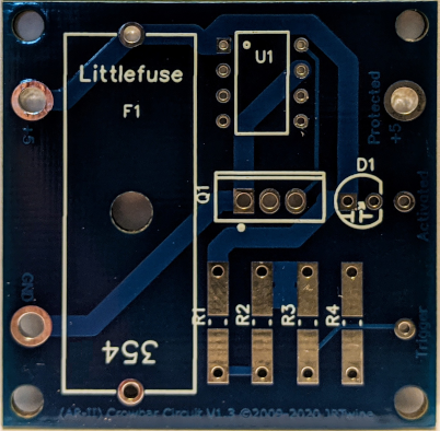
Anyone that says that simply performing the SENSE mod is bulletproofing1 an A/R-II is lying to you or just does not know any better. Why? Because if the +5V regulation fails it is still possible to end up with more than +5V over the +5V line, which could damage any board connected to it. What kind of “bulletproofing” is that? (Shameless plug: that is why I designed a PCB with an adjustable crowbar circuit – THAT is how you bulletproof an A/R-II!) Anyway – rant over… information on an easy way to perform the SENSE mod is shown below where I document connector J7.
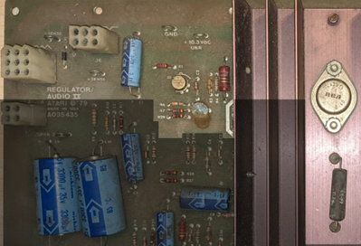
Meet the Atari Regulator/Audio II (mod -02)
This component, affectionally referred to as the A/R-II (“A Are Two” even though calling it the R/A-II would be more correct) was used in many of Atari’s games from the ‘70s and ‘80s. It exists in various forms, from the original Regulator/Audio board used in early B/W games like Asteroids and Atari Football, to the Regulator/Audio II used in many different color games to about the mid ‘80s (e.g. Centipede, Dig Dug, Kangaroo, Missile Command, Pole Position, Tempest, etc.), to the Regulator/Audio III.
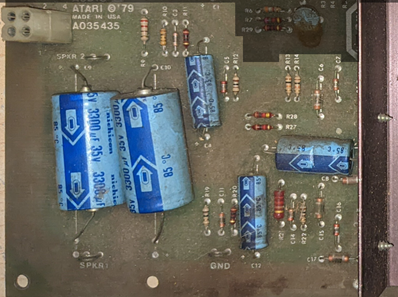
Its primary purpose was to supply necessary voltages for the game (logic, audio, and sometimes things like the odd voltages required to erase an EAROM), as well as provide audio amplification. Different versions of the board provided different features like different voltages, more amperage, etc. The image below shows a -02 version.
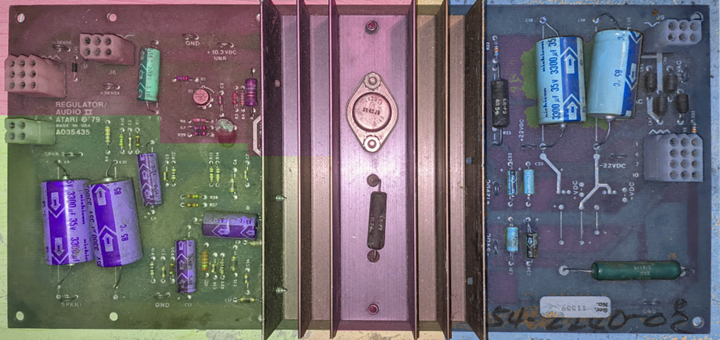
Figure 1 – AR-II Sections
The board can be roughly divided into 3 areas that are shaded purple, green, and bluein the above image. The middle and upper-left areas are +5V regulation, the lower-left is audio amplification, and the right side is secondary voltages (-5V, +12V, and +/-22V). It is worth mentioning that both “halves” of the board are logically separate. You can apply power to only the left side and get your +5V and audio amps. And you can apply power to only the right side and get your secondary voltages. Both sides do not have to be powered up at the same time.
The connectors are consistent between other versions and revisions of the board, so it may be possible to substitute one for the other depending on the voltages and/or features required. For example, a -03 can usually be used to replace a -02.
Connectors
We will go through the connectors in order of their designations.
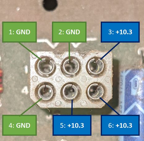
J6 – Main Power Input
Figure 2 – AR-II Connector J6
This connector supplies the power required to produce the regulated +5V and audio amps. Note that the +10.3VDC input is unregulated and may normally measure a couple of volts higher when not loaded, such as if you meter it directly on the power brick.
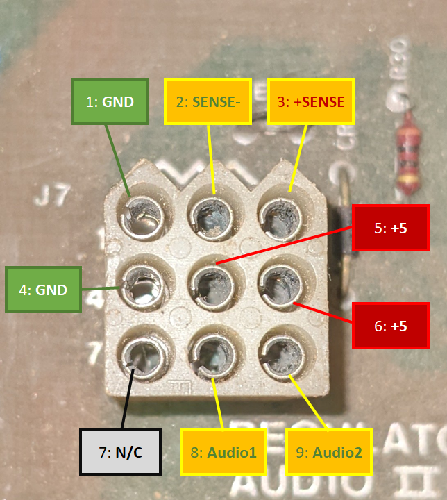
J7 – Main Power Output and Audio Input
Figure 3 – AR-II Connector J7
This connector supplies the regulated +5V as well as the SENSE lines. It also is where unamplified audio comes into the board.
SENSE Circuit Description and the SENSE Mod
So, how about we stop here for a second to talk about SENSE. You may have heard of the infamous SENSE circuit on these boards, but what does it really do? Well, it is supposed to detect a voltage drop between the power supply and the game’s board. On the game’s PCB the +5V is routed to +SENSE, and GND (the +5Vreturn) is connected to -SENSE. The A/R board uses the voltage coming back on the SENSE lines to determine if it needs to bump up the voltage to compensate for any voltage drop that occurred on the way to the game’s PCB. Sounds like a good idea at first, right?
Well, now throw in a failing +5V connection to the board – like a dirty connection or a physically failing one. As more and more voltage is lost, the SENSE circuit will keep boosting the voltage, which can lead to overheating and exacerbate the failing connection. Remember that the +5V and +SENSEare connected on the game board? Well, if the +5V connection fails badly enough, the game might try to draw current over the +SENSEline. This is the cause of the infamous smoking of R30 (and sometimes R29) – the game is trying to draw multiple amps across that poor little ¼ or ½ watt resistor.
So, the SENSE mod tricks the SENSE circuit into always seeing exactly what the A/R board is putting out. This is done by connecting +5V and +SENSEtogether, and GND and -SENSEtogether, on the A/R board itself. The easiest(?) way to do this is to turn the A/R board over and solder a jumper between pins 1 and 2, and another one between 3 and 6 on connector J7. Note that after doing this, you may have to manually adjust the +5V pot to get a solid +5V at the game board.
It is also worth noting that if you ever need to bench test the board or adjust the voltage using the pot at R8, make sure that the +SENSEline is connected back to the +5V line either via the mod or by connecting-up a game board. The +SENSEline is what is connected to the feedback input on the +5V regulator and and this feedback circuit is necessary for the board to work correctly.
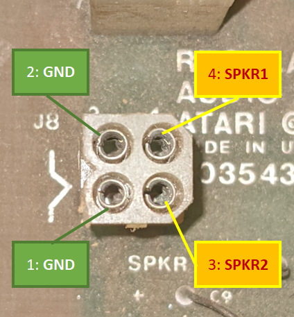
J8 – Speaker (Amplified Audio) Output
Figure 4 – AR-II Connector J8
This is the amplified audio (Speaker) connection. If you are used to seeing positive and negative speaker signals, consider the SPKR1 and SPKR2 signals to be the positive ones, and the GND to be the negative ones.
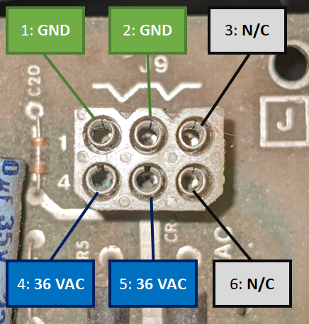
J9 – Secondary Power Input
Figure 5 – AR-II Connector J9
This connector provides the 36VAC (note – AC,not DC like on J6) input voltage to the board which is necessary to generate the additional +12, +/-22, +/-15, and -5 voltages. Not all A/R boards are stuffed to produce all the secondary voltages. On the board shown in this document, the area that would be used to produce the +/-15V is unpopulated.
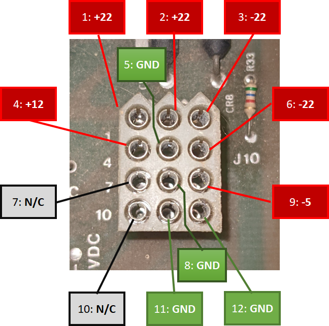
J10 – Secondary Voltage Output
Figure 6 – AR-II Connector J10
This connector provides the additional voltages produced from the 36VAC provided on connector J9. (Pins 7 and 10 would be the +/-15V if it was present on this board.) Also note that the +/-22Vis unregulated and directly connected to the bridge’s filtered output, so do not be surprised if you see a higher voltage when unloaded.
Operation
Here I will try to describe how this A/R board works.
Primary +5V Supply
The primary +5V supply derives from the +10.3VDC input to the left side of the board. This uses a LM305 regulator marked Q1 and transistors Q2 and Q3 to boost the output current. Q2 (a TIP32) acts as a driver for the larger Q3 (a 2N3055).
Excessive voltage or no voltage on the +5V line may be caused by a failed 2N3055 or a failed LM305. Suspect the 2N3055 if you have +5V present, but it drops when you load the +5V line. If you have no +5V output and the audio amps also appear to not be working, verify the +10.3VDC input voltage from the powerbrick.
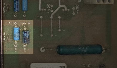
Figure 7 – AR-II Primary Voltage Area
Audio Amplifiers
Audio amplification is provided by the two TDA2002(AV) amplifiers.
If you are having problems with distorted sound, I would start with the two larger output coupling caps, C9 (SPKR1) and C10 (SPKR2) before looking at the amplifiers themselves.
Figure 8 – AR-II Amplifier Area
Secondary Voltages
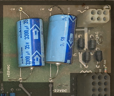
The secondary voltages derive from the 36VAC input to the right side of the board. This AC goes through a traditional full-wave bridge rectifier constructed using four discrete diodes (CR5, CR6, CR7 and CR8) with the two large smoothing caps C18 and C19. Its output is used to produce all the secondary voltages. If you notice excessive ripple on any of the secondary voltages, especially the +/-22Vones, check C18 and C19.
If you notice a sudden voltage drop on the secondary voltages, or a complete loss of one of the polarities, check for failed diodes in the rectifier (i.e. the full-wave rectifier may have become a half-wave rectifier).
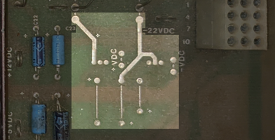
+/-22V Unregulated Supply
This is directly connected to the post-smoothed rectifier output. If the incoming 36VAC is good and all the rectification and filtering is working correctly, you should see these voltages. These outputs might be the best ones to look at to help spot rectification and filtering issues. Remember this is an unregulated output so you may see a higher voltage here when unloaded.
Figure 9 – AR-II Secondary Voltage Input
+/-15V Supply (Not present on this board.)
These voltages are produced by two regulators that use the unregulated +/-22V as inputs. The positive regulator is a 7815 and is connected to the positive side of the unregulated +/-22V, and the negative one is a 7915 that is connected to the negative side of the unregulated +/-22V.
Figure 10 – +/-15V Voltage Area
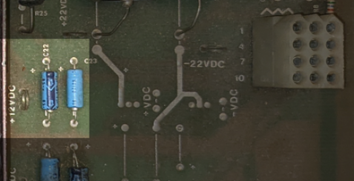
+12V Supply
This voltage is produced by a 7812 regulator connected to the positive side of the unregulated +/-22V.
Figure 11 – +12V Supply
– 5V Supply
This voltage is produced by a 7905 regulator connected to the negative side of the unregulated +/-22V.
Figure 12 – -5V Supply
Troubleshooting
This section covers a few things that might help with troubleshooting and repair of an A/R-II.
First is a good adjustable power supply to produce the +10.3V for the primary side and either a transformer that will output ~36VAC or a variable one for the 36VAC for the secondary side. I recommend working with one side at a time.
Next is to get a good quality 2-ohm, 20 W cermet resistor. When briefly connected between +5V and GND it will pull 2.5 amps and I believe this is a suitable load to test the +5V line with.
If testing on a bench, be sure to either have the sense mod performed or jumper together the +SENSE and +5V pins, and the -SENSE and GND pins.
Problem/Symptom
Possible Cause(s)
+5V is present and seems stable when measured while unloaded but drops to a much lower voltage when loaded.
1. The 5V regulator may have failed.
2. The 5V regulator is working, but the board cannot provide the additional current that would normally be provided via Q2 and/or Q3, so one or both may have failed (likely just Q3).
No +5V present, audio amplification seems to be working.
1. This could mean that the 5V regulator has failed.
2. This could mean that the 5V regulator is working, but the board cannot provide the additional current that would normally be provided via Q2 and/or Q3, so one or both may have failed (likely just Q3).
No +5V and no audio amplification.
Check 10.3VDC input and fuses on power brick.
One or more audio channels is not working.
The amplifier for that audio channel may have failed – the TDA2002 at Q5 for SPKR1 and/or the one at Q7 for SPKR2.
One or more audio channels are distorted.
The output coupling cap for that audio channel may be leaky and need to be replaced – C9 for SPKR1 and/or C10 for SPKR2.
+5V has excessive ripple present or the game is experiencing excessive crashes, resets, visual artifacts, odd behaviors, etc. Sometimes an audio hum can also be heard.
Check the large filtering capacitor (the “Big Blue”) on the power brick.
Secondary voltages have excessive ripple present (especially noticeable on the +/-22V).
Check the two large filtering capacitors on the right side of the board – C18 and C19.
Secondary voltages are missing a polarity or a reduction in output is voltage is present
One or more of the diodes that comprise the full-wave bridge rectifier on the right side of the board may have failed – CR5, CR6, CR7 or CR8.
Missing one or more of the regulated secondary voltages.
The regulator for the associated voltage may have failed – the 7905 for the-5, or the 7812 for the +12.
Pulling too much current on the 36VAC (blown fuses).
One or more diodes in the bridge may have shorted – CR5, CR6, CR7 or CR8.
Component Layout and Parts List
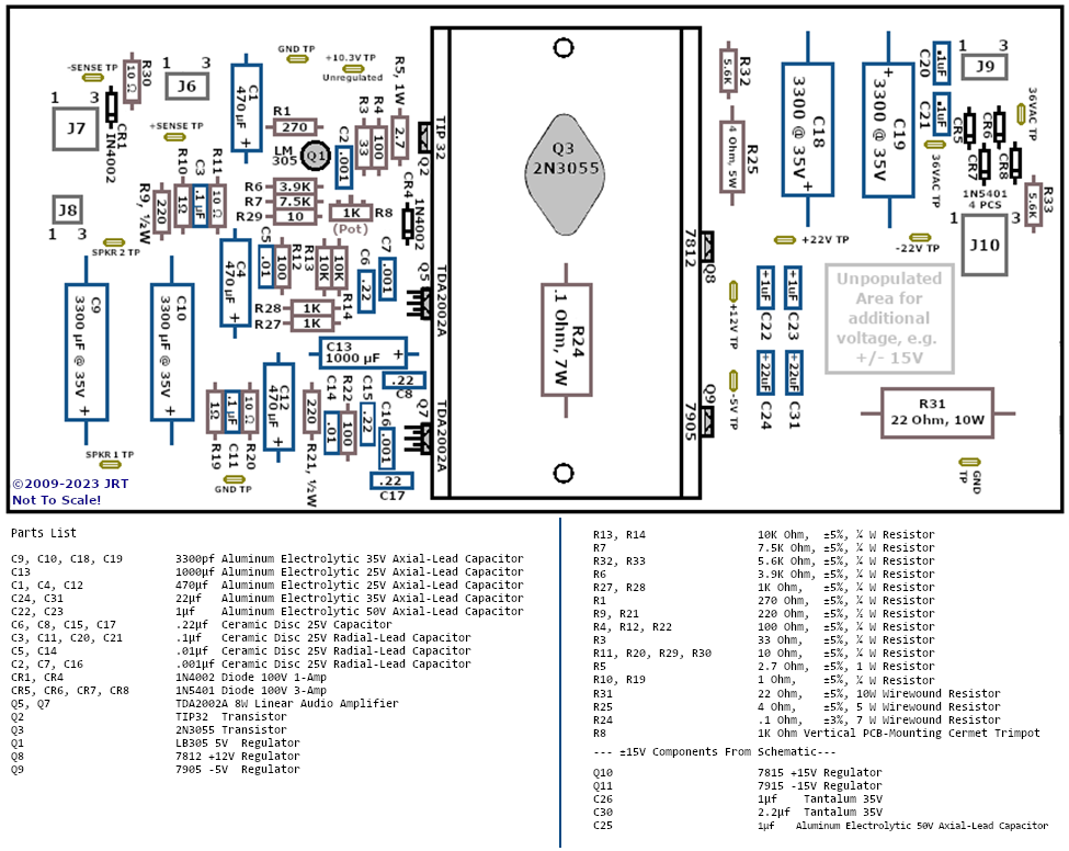
The following is a redrawn parts layout for this A/R-II board. Location may not be precise or exact down to a millimeter but should allow you to locate and identify components of interest. A parts list is also included.
Figure 13 – AR-II Layout and Parts List (Click for full size image)
Modifications
Converting a -02 to -03
The version -03 of the AR-II is almost identical to the -02 but with a few changes for the increased current demands of Missile Command (and Monte Carlo?). The differences are:
R25 – a 4 ohm 5W resistor, is replaced with a jumper (or you might see a black zero-ohm resistor)
R31 – a 22 ohm 10W resistor is replaced with a 15 ohm resistor
This also means that you should be able to safely substitute a -03 for an -02 if necessary.
[1] You do not wear a bulletproof vest to prevent things from going wrong, you wear one for when things do go wrong. If you are not able to completely prevent or robustly handle a catastrophic failure, I would suggest that you are notbulletproofing.
Well, like the title initially asks, can you really “bulletproof” an Atari AR-II board? From what I have found on the Internet, and older material like Star Tech Journals, the answer really is no. Pretty much all sources that mention “bulletproof” and “AR-II” on the same page are only taking about performing the Sense mods, and nothing else.
A small amount of pages mention replacing parts (caps, regulators, etc.) due to their age, but that is not bulletproofing either – that is just a good idea. But I think I can actually bulletproof it, and maybe other power supplies as well.
So this is basically the second part of a previous post about a tempest that lost deflection.
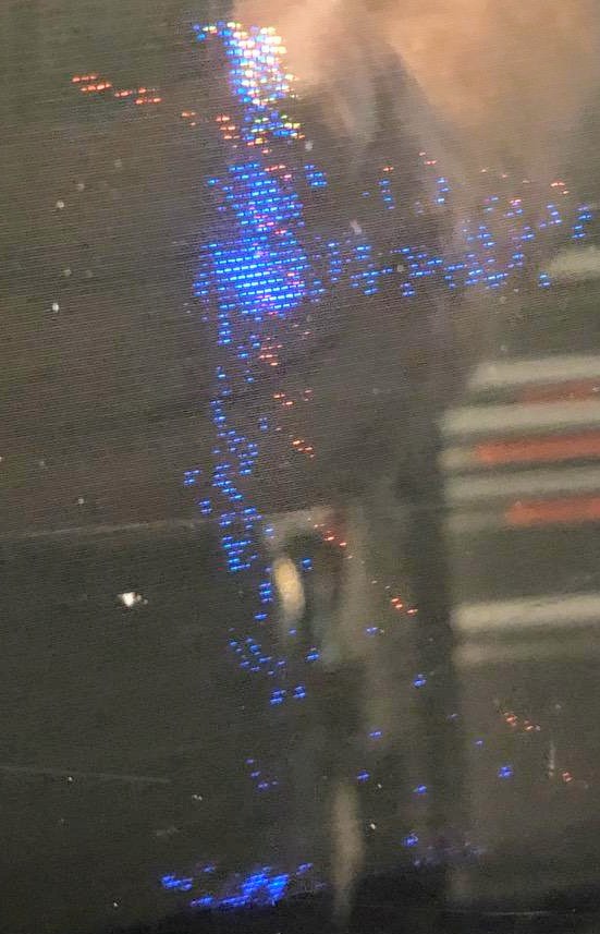
After running for a while that Tempest’s display changed into something that can only be described as a tangled mess:
Tempest Tangle
That is something that I never had seen before. The owner turned the game off and back on again later that day and it was working normally. Then it would get screwed up again.
So I was helping a newly minted arcade game owner when his first purchase, which is his favorite arcade game: Tempest. Shortly after getting it the X-Size pot fell apart and the game ended up only showing a Multicolored spot (larger than a just a “dot”) which changed depending on what the game was doing. We soldered in a larger replacement (dangling from some wires) but while this did change the display a little when the pot was articulated, it did not fix the problem.
He had joined a FB arcade repair group and asked for help there and ended up with ideas ranging from his brightness being too high (it was not – I think the person that responded thought the game was drawing normally but with retrace lines and a white dot in the middle, kind of like how it looks when you’re drawing on an oscilloscope with no Z input), voltages too low (they were not), and one even going down the path of impending AR-II failure(!) and going on about replacing leaky sense resistors and the bottlecap transistor. Oy vey!
Got to work on a busted Centipede that booted to a white background screen that briefly showed the start of the attract mode (things drawn in green or purple) before crashing, watchdogging and doing it all over again. Test mode would do the same thing as well.
Disabling the watchdog (by grounding the WDDIS test point) did not help as the game would just essentially do the same things but just not reset after it crashed.
Going through my boards, I came across a second Dig Dug board. This one boots to static garbage and no sound. Watchdog is barking.
Removing one of the CPUs gets different garbage. Tried replacing with a known good one, no change.
Checking the pins shows me that a couple of the data lines, from D3 to D6 (I cannot remember which ones right now) are completely floating! Rarely see that. On a hunch, I replace the CPU’s socket, but this changes nothing.
Board traces go two a few chips (a 7474 and some other multiplexers or demultiplexers), and the floating lines seem to follow them. But following the traces is tricky, so I gotta dig up some schematics to see what the Hell is going on.
My previous post, about Cocktail #1, clearly documents the “easy one.” This second one is gonna be another story. It has a very dead monitor, and a non-functional board. I have not yet benched the monitor, but it has no neck glow, which is never a good sign.
The board has problems, but at least I know it is not the CPU as I already swapped it, and I know that it is not a power problem on the second Cocktail, because the board has the same behavior in Cocktail #1.
Swapped all socketed chips to no effect — they all work on the other board. Power points seemed right on the board, but I put it into my working cabinet to verify… and while doing so I managed to cross GND with a +5v trace and smoked R30 quite nicely on my AR-II board.
I have replaced it, but am still getting voltages that are too high. Gonna have to hunt other likley suspects…
As far as the board goes, I am gonna have to break out the Fluke 9010 to work on this one… Right after building an adapter for it so I cam power it up on the bench.
The monitor I should know more about once I have it on the bench and take a good look at it while I am capping it (and doing the sync upgrade).
—–
Turns out that this one had a cracked flyback. I ordered a replacement kit (flyback and caps) from The Real Bob Roberts and replaced the flyback (my first flyback replacement!). Have not yet put it back into the game and fired it up, though. Maybe after winter…
Well, I ended up taking two Centipede cocktails off of another local collector as a package deal. Still want that Gorf, though… Will have to come back to that one soon!
But I digress… So I have two Centipede cocktails here. One of them has a dead monitor (and a non-working board, I later discovered), and the other will not sync:
(Note how dirty the control panel is, as well as the color of the button and trackball to compare with another picture later in this post.) Checked the wiring, the connectors, adjustments/controls and nothing would get it right, so I went to capping it. Here is a picture of it half way done on my bench:
After capping it (and also doing the sync improvement upgrade while I was there), all it took was a few adjustments and the screen came up sharp and clear. This image also shows one of the rebuilt trackballs, which is now running as smooth as when it came out of the crate:
The text looks a bit blurry, but only in the picture. The screen is really sharp! You can also see a new shiny trackball at the bottom too. Next to it is a really dirty button. Here is one of the panels (from the other cocktail, because its panels are in better condition) with a replacement button and a (unmounted) rebuilt trackball after being cleaned up a bit:
All in all, not bad for about 3 or so hours of work, if I do say so myself. (3 hours for everything, not just cleaning this panel! 🙂
Now, that other cocktail… that one is gonna be a bit harder…
Problem: Stiff spinning steering modules and hard shifting between gears
(Quick little story – while bringing this beast into its location, I fell and got pinned under it for a few minutes. It is amazing how much having your chest compressed effects your ability to call out for help! 🙂
OK – onto the next issue… Its steering wheels were pretty stiff, and if you tried to give them a good hard spin they would come to a halt within a couple of turns. Removing and disassembling them was easy. Turns out the problem was that the old grease in them had coagulated/thickened so that it was about as viscous and sticky as cold honey!
Getting the grease out of the barrel and off of the shaft and sleeves literally took ~10 minutes (for each module) with some rubbing alcohol, elbow grease and rags. I had a friend helping me (Sean) and we each tackled one sterring wheel each.
After getting that old gunk out, a quick application of some light lithium grease on everything solves that problem – the wheels will now spin for at least 10 turns easily.
For the shifter modules, I just applied some powered graphite to the shifter “ball” at the opening of the shifter and after a few shifts to get it all around, the shifts are much easier now.
Solution: Cleaned and lubricated the steering modules, lubricated the shifter modules.
Note: One of the steering modules has a broken shaft/cone, which caused the wheel to be off-center, and it was being held in place strictly by the force of the retaining bolt that goes through the entire assembly. I managed to get it a bit straighter than it was before, but it still is broken internally. Not sure if I want to go through sanding down the two halves to try to get them melded or epoxied together – I am afraid of shortening the cone too much and causing problems. The wheel works and the game is playable, so I might just leave it as it is.
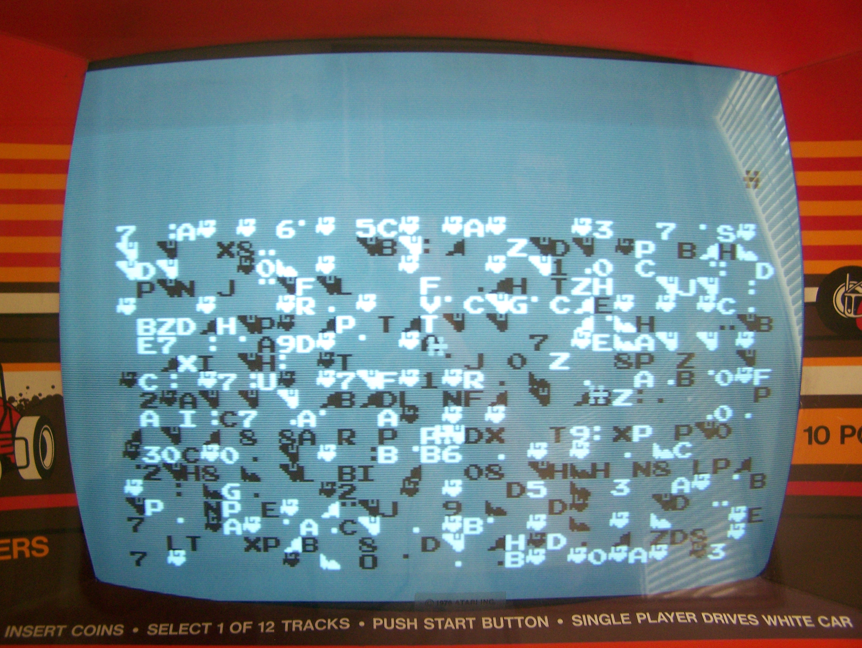
Purchased a Sprint 2 in non-working condition. Saw a picture of it, monitor worked – it showing what appeared to be static garbage on it. Got it home and confirmed that yes, it is showing static garbage (first image below). Turning it off for a couple of seconds and then back on again keeps pretty much the same garbage display, but sometimes gets some sounds out of it (engine and/or screeching sounds). Moving the self-test switch does nothing. First suspect that CPU is not running, because the screen is static (i.e. not changing while the game is on).
After checking the usual suspects (voltages, loose wires, harness/wire burns because this is an older Atari game…), I yank the CPU to see if I get the same results (to narrow it down to the CPU). This causes a different effect, a screen filled with a single character and I get sound, so I presume for now that the CPU is working and the problem lies elsewhere.
I bought two or three sets of unknown/untested/bad boards sometime last year. I have recently started going through them to determine the severity of their problem(s). (This is taking a surprisingly long amount of time due to the time it takes to create a JAMMA adapters for each unique interface! :/ )
Anyhoo, I came across a complete, intact Kangaroo board last weekend! After creating a minimal adapter (Power and Video), the board came right up! I tried its self-test and it passed. After watching the attract mode for a little bit (~30 seconds), the game started to show some visual artifacts on the RHS of the screen. They were horizontal blurbs that looked like multicolor static. However, each of the blurbs, while in a random vertical location, were identical.
Purchased described as “Has a ROM error“. Started by creating a JAMMA adapter, and then read the EPROM at 2E, it was not found under Romident, burned and installed a replacement. No change. Removed and read all ROMs in row/column 2, and all but one of them failed to be identified by Romident, burned and installed 5 more replacements, working! Still have to wire up an amplifier to correctly test the sound, but looks good so far.
[07/30/03] I finally found the brain cell that got me to realize that I could use my inductive listener (a telecom tool, often used with a tone tracer) to test the sound. It works!
Solution: Replaced bad ROMs
(Recently, the board is starting to develop an intermittent problem with a bad socket. I am going to replace it as the first use of my soon-to-be-here combination soldering/desoldering station.)
Blog Site for myself, and my friends
Spam Karma 2 has sent 0 comments to hell and 0 comments to purgatory. The total spam karma of this blog is 0. What's your karma?